
How to Read 3D Printing Accuracy and Tolerance: What Affects It and How to Inspect


Asking about 3D printing accuracy and getting a single number back is not much use. Accuracy depends on the process, the material, the size of the part and the finishing method — the same machine can deliver noticeably different results on different parts. This article covers what drives accuracy, what the common processes achieve, and how to agree an inspection method.
1. Accuracy is not a fixed number
Many people assume “how accurate is this machine” has one fixed answer. It does not.
- The forming principle sets the baseline — SLA has the better dimensional accuracy and surface finish, SLS / MJF sits behind it, and FDM shows the most visible layer lines.
- The bigger the part, the bigger the absolute deviation — small parts hold accuracy more easily, while large parts are more affected by shrinkage and support.
- Finishing changes dimensions — sanding, polishing and painting all touch the surface and small features.
- Orientation and nesting matter too — turn the same part to a different angle and the accuracy of a critical face can change.
So the right question is not a general machine figure but: “on this part, at this dimension, on this face, what can you hold?”
2. What the common processes typically achieve
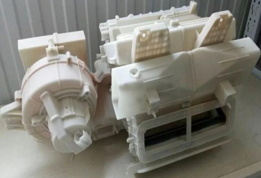
The tolerance ranges below are a cross-process reference only; the actual result depends on the part and the inspection method.
- SLA — high detail, small parts typically in the ±0.1mm range, suited to fine structures and appearance parts.
- SLS / MJF powder-bed nylon — affected by powder particle size and shrinkage, generally ±0.3mm or ±0.3%, whichever is greater.
- FDM — visible layer lines and the lowest accuracy of the group; good for structure checks, not for precision fits.
- SLM metal — density can reach above 99.5%, with dimensional accuracy between resin and powder bed; mating faces normally keep machining allowance.
- CNC machining — as a reference point, high-precision mating faces can be held to ±0.01mm, which is why critical mating faces are often “printed first, finished afterwards”.
One thing worth seeing clearly: the more accurate the process, the higher the cost and lead time tend to be. Not every face needs the highest accuracy — allocating it where it is needed is what pays.
3. What affects accuracy
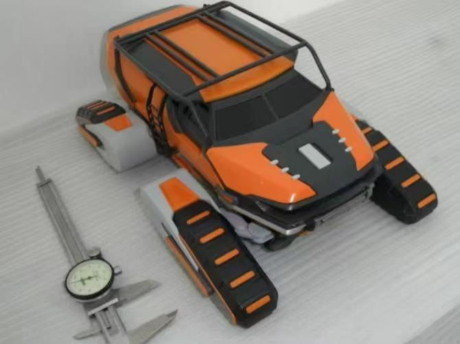
- Orientation — coaxality and flatness are directly tied to build direction, so critical faces need their direction fixed in advance.
- Shrinkage and compensation — both powder bed and resin shrink, and compensation has to be applied by material and direction.
- Support position — supported faces pick up marks, which affects local dimensions and appearance.
- Environment — resin parts are sensitive to temperature, humidity and post-curing time; insufficient post-curing affects long-term dimensional stability.
- Material — shrinkage differs between grades, so a material change means re-confirming critical dimensions.
4. How to agree on inspection
If inspection is left vague, it tends to end in argument. Settle these points up front:
- Mark the critical dimensions — separate mating dimensions from appearance dimensions and state requirements for each, rather than asking for everything to be “accurate”.
- Leave machining allowance on critical mating faces — print first and CNC-finish after is more reliable than printing the face directly.
- Agree the measuring method — callipers, optical comparator or CMM give different conclusions, so say which applies.
- Give a tolerance band rather than a single value — a reasonable spread is easier for both sides to work with.
- Agree the acceptance basis — the drawing, the first-article check, or the assembled result; decide before the job starts.
5. Primofort’s accuracy control and inspection
Primofort‘s processes span SLS / MJF powder-bed nylon, SLA, SLM metal, FDM and full-colour PolyJet. SLM metal parts reach above 99.5% density, and CNC finishing holds ±0.01mm. Printed parts go through a first-article check against critical dimensions, and where a mating face needs more accuracy we can combine printing with finishing in one sequence. How far a specific part can go is assessed together with its geometry and size.
6. Requirements that should not go straight to printing
- Mating faces that need a mirror or high-gloss finish.
- Tolerance bands outside the capability of a printing process.
- Precision fits that must hold dimensions over the long term.
- The combination of large size, thin walls and high accuracy — these normally need to be split, or moved to another process.
Conclusion
Send the drawing (STL, STEP or IGS are all fine) together with the critical dimension requirements, and Primofort can first assess which dimensions print directly and which are better left with allowance for finishing, then quote. If you have inspection reports or acceptance standards, share those too so the expectations match from the start.